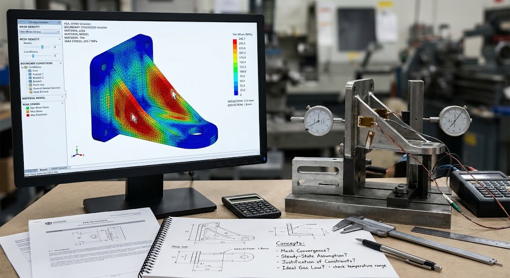
A finite element model can return a beautifully smooth stress plot and still be wrong in a way that costs marks nobody explained clearly enough during the module. The number on screen looks authoritative precise to several decimal places, colour-coded, confident. Whether it means anything depends entirely on choices made before the solver ever ran: the mesh density, the boundary conditions, the material model, the assumptions baked into the geometry simplification. This is where a lot of final-year mechanical engineering reports quietly fall apart, not because the analysis is wrong, but because the reasoning behind it never makes it onto the page.
Understanding the Topic
Documenting simulation and calculation work properly sits right at the point where mechanical engineering students shift from running software to justifying engineering decisions. Third and fourth-year modules covering FEA, thermodynamics, and CAD-based design reports increasingly assess not whether a student can produce a result, but whether they understand what that result actually represents and where its limits lie.
This matters because industry and academia both treat a raw output as incomplete. A stress value without its boundary conditions, or an efficiency calculation without its stated assumptions, tells an assessor almost nothing about whether the engineer behind it understood the physics involved. Reports at this level are marked on judgement as much as on numerical accuracy, and that shift catches a lot of students off guard after years of coursework where a correct final answer was often enough.
Common Problems or Concerns
The most common issue is presenting a converged mesh result without showing that convergence was actually checked. A single mesh run, however fine, doesn’t demonstrate that the solution is stable it only shows what one particular mesh produced. Markers looking for evidence of mesh independence studies frequently find none, and the analysis loses credibility regardless of how plausible the final number looks.
Boundary conditions cause trouble of a different kind. Students often apply a fixed constraint or a simplified load case because it’s what the tutorial demonstrated, without explaining why that simplification is reasonable for the specific component being analysed. A cantilevered bracket modelled with a perfectly rigid wall support, for instance, rarely matches how the part actually mounts in practice, and failing to acknowledge that gap suggests the simplification wasn’t a deliberate choice at all.
Thermodynamic calculations expose the same weakness in a slightly different guise. Assuming ideal gas behaviour, steady-state conditions, or negligible heat loss might be entirely appropriate but only if the report says so and explains why. Left unstated, these assumptions read as oversights rather than engineering judgement, even when the underlying physics reasoning was sound.
Key Theories or Concepts to Know
Mesh convergence testing is the backbone of credible FEA work: running the same simulation across progressively finer meshes and tracking whether the result of interest stress, deflection, temperature stabilises rather than continuing to shift. A result taken from an unconverged mesh is, strictly speaking, unverified, whatever the plot looks like.
Boundary condition justification asks a related but separate question. Fixed, pinned, and free constraints each carry assumptions about how a component actually interacts with the structures around it, and choosing between them should trace back to the real geometry and loading path, not just the nearest available option in the software’s constraint library.
For thermodynamic work, closed versus open system boundaries, steady-state versus transient conditions, and the validity of ideal-gas assumptions under the given pressure and temperature range are the recurring concepts examiners check for. CAD-based design reports, meanwhile, tend to be assessed on tolerancing decisions and manufacturability reasoning whether a chosen fit or feature reflects an understanding of how the part will actually be produced, rather than default software settings left unchanged.
Key Factors to Consider
The quality of a simulation-based report tends to come down to how transparently the underlying decisions are documented, rather than how sophisticated the software or the geometry happens to be. A relatively simple analysis explained with full reasoning about mesh choice, constraints, and material properties will usually outperform a more elaborate model presented with no justification at all. The trouble is timing: FEA and thermodynamic reports often land in the same weeks as lab write-ups and design coursework, and a proper mesh convergence study or a fully reasoned set of boundary conditions takes longer to build than most students plan for. That squeeze has made expert mechanical engineering coursework help a familiar search term among students trying to see, before their deadline, what a fully justified, properly documented simulation report actually looks like in practice. What’s worth taking from that isn’t the numbers but the reasoning pattern behind how the report is structured.
Practical Guidance
Run at least three mesh densities and present the trend, not just the final value, showing how the result of interest changes as element size decreases and where it levels off. State explicitly which mesh was used for the reported result and why that level was judged sufficient rather than simply the last one attempted before time ran out.
For boundary conditions, sketch or describe the real mounting or loading arrangement before explaining how it was simplified for the model, and note what that simplification might be hiding stress concentrations at a support, for example, that a perfectly rigid constraint won’t capture. In thermodynamic calculations, state every assumption as a sentence in its own right rather than leaving it implicit in the working: “steady-state conditions were assumed because the process duration exceeds the system’s thermal response time” does far more for a mark than the same assumption sitting unstated behind a formula.
Mistakes to Avoid
Treating a solver’s default settings as correct without questioning them is a frequent and costly habit. Default time steps, convergence criteria, and material properties are starting points, not validated choices, and a report that never questions them signals that the defaults were never actually understood.
Another recurring mistake is comparing simulation results to reality only in passing, or not at all. A report that never asks whether the predicted stress or temperature is physically plausible checked against hand calculations, known material limits, or published data misses the step that distinguishes engineering analysis from software operation.
Students also sometimes overstate confidence in a single result, presenting one mesh, one load case, and one set of assumptions as though it were the only possible answer. Acknowledging where the model could reasonably produce a different result under slightly different assumptions tends to read as stronger engineering judgement, not weaker analysis.
Bringing the Main Lessons Together
A simulation result only becomes an engineering argument once the reasoning behind it is visible on the page the mesh convergence shown, the boundary conditions justified against the real geometry, the assumptions stated rather than buried. None of that requires more advanced software or a more complex model. It requires treating every number as something that needs defending, not just displaying.
Rate this business
Have you heard of this business? Do you like it? How do you like it?
Check out if it is in the list of Top Rated Small Businesses